|
Input A
|
Input B
|
LED 1
|
LED 2
|
Picture
|
|
High (1)
|
High (1)
|
Off (0) Low- ground
|
On (1) High- 5 volts
|
|
|
High (1)
|
Low (0)
|
On (1) High- 5 volts
|
Off (0) Low- ground
|
|
|
Low (0)
|
High (1)
|
On (1) High- 5 volts
|
Off (0) Low- ground
|
|
|
Low (0)
|
Low (0)
|
Off (0) Low- ground
|
Off (0) Low- ground
|
|
Extra Information
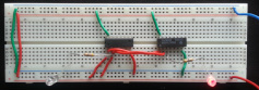
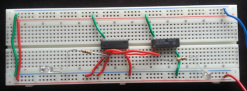
Looking at the Truth table for this chart there are combinations that turn ON and OFF the two LEDS. If we let LED 1 represent the LED connected to the 7408 IC chip and LED 2 represent the LED connected to the 7486 IC chip then we can better help look at the four different cases in lab 12. The first case of inputs in Lab 12 that was observed was when the two inputs were both ground (0) in this situation both LED 1 and LED 2 were OFF. In the second case of inputs in Lab 12 that was observed was when Input A was on High (1) and Input B was on ground (0) in this situation LED 2 was seen ON while LED 1 was still seen OFF. In the third case of Inputs in Lab 12 that was observed was when Input A was on ground (0) and Input B was on High (1) in this situation LED 1 was OFF and LED 2 was again seen ON. In the last situation that was observed in Lab 12 Inputs A and B were both on High (1). In this situation LED 1 was seen on while the LED 2 was seen off.
Looking at the Truth table for this chart there are combinations that turn ON and OFF the two LEDS. If we let LED 1 represent the LED connected to the 7408 IC chip and LED 2 represent the LED connected to the 7486 IC chip then we can better help look at the four different cases in lab 12. The first case of inputs in Lab 12 that was observed was when the two inputs were both ground (0) in this situation both LED 1 and LED 2 were OFF. In the second case of inputs in Lab 12 that was observed was when Input A was on High (1) and Input B was on ground (0) in this situation LED 2 was seen ON while LED 1 was still seen OFF. In the third case of Inputs in Lab 12 that was observed was when Input A was on ground (0) and Input B was on High (1) in this situation LED 1 was OFF and LED 2 was again seen ON. In the last situation that was observed in Lab 12 Inputs A and B were both on High (1). In this situation LED 1 was seen on while the LED 2 was seen off.